Comparison of Head Types: Hemi, SE, F&D, and Flat
Upload Time:
Dec 09, 2024
A cylindrical shell is fabricated using 0.500-inch-thick SA-516 Grade 70 material, which is rated for 20,000 psi at 100°F. The shell is rolled to an outside diameter (OD) of 48 inches, resulting in an inside diameter (ID) of 47 inches. The cylinder, along with the seams connecting it to any attached heads, undergoes full radiographic inspection. No corrosion allowance has been factored into the design. According to ASME Section VIII, Division 1, the calculated design pressure for this cylinder is 420 psi.
Pressure vessels commonly use four types of heads: Hemispherical (Hemi), Semi-Elliptical (SE), Flanged and Dished (F&D), and Flat. In this analysis, each head is considered as being attached to a cylindrical shell, with their inside diameters (ID) matching the cylinder's. The wall thickness for each head is adjusted to meet the cylinder's 420 psi design pressure. Detailed calculations can be accessed via the link provided below.
The results include the wall thickness, overall height, internal volume, and weight of a single head, factoring in any straight flanges when applicable:
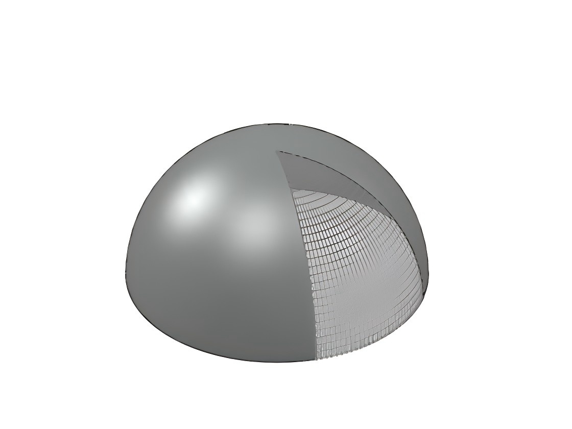
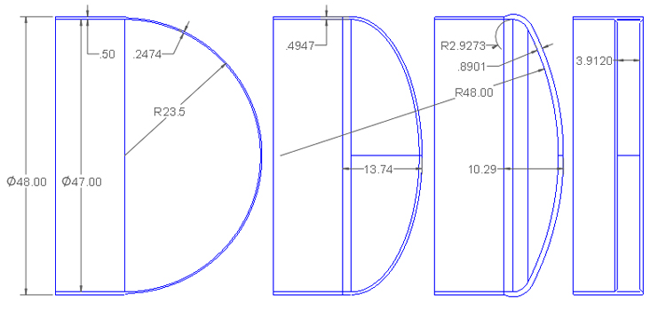
The hemispherical head features a simple radial geometry, with a depth equal to half its diameter. For a head with a 47” inside diameter (ID), the required wall thickness is 0.2474”, which is about half the thickness of the cylindrical shell. Since the head is thinner than the shell, a standard ASME code-compliant 3:1 taper is applied at the transition. This taper is part of the stronger head, while the cylindrical shell maintains its full thickness along the straight section for strength.
Hemispherical heads are typically not formed from a flat plate but are instead fabricated from welded segments. This makes them the thinnest yet sometimes the most expensive head type. They are commonly used in high-pressure or large-diameter applications where material savings are critical. Additionally, two hemispherical heads joined back-to-back create a storage sphere, the most efficient shape for pressurized storage.
The semi-elliptical head has an elliptical shape, with the most common ratio being 2:1, where the width of the ellipse is twice its depth. In practice, fabricators often use three radii to approximate the ellipse: a large radius at the crown, a small radius at the outer edge, and an intermediate radius in between. ASME code rules specify how closely the fabricated head must approximate a true ellipse.
For a 2:1 SE head, the depth is one-quarter of the diameter, making it shallower than a hemispherical head but deeper than flanged and dished (F&D) or flat heads. This head can be formed from a flat plate, making it one of the most economical options for low-pressure vessels.
Although less efficient than the hemispherical head in handling stresses, SE heads require slightly more thickness. For example, the required thickness for a 2:1 SE head in this case is 0.4947”, slightly less than the 0.500” thickness of the cylindrical shell.
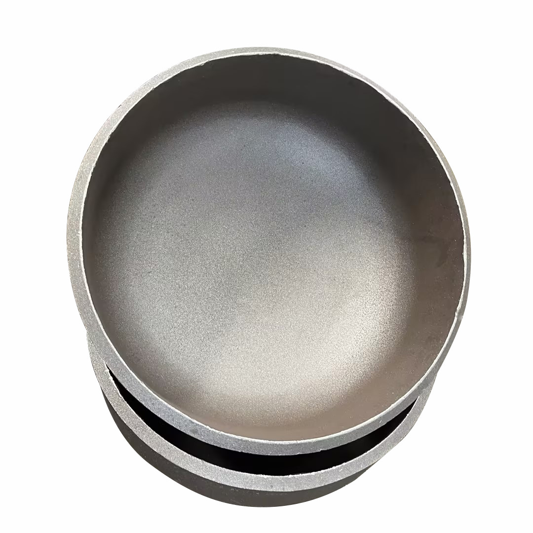
Flanged and dished heads are commonly used in moderate-pressure applications where minimizing height is important. In this design, the crown radius equals the cylinder’s outside diameter (48”), and the knuckle has a tight 2.973” radius. This results in a head with a lower profile than the semi-elliptical head. However, the tight knuckle radius induces high forming stresses, requiring post-forming heat treatment for stress relief.
The F&D head requires a thicker wall than the cylinder, with a required thickness of 0.8901”. A standard 3:1 taper on the straight flange section of the head handles the transition, as the flange portion only needs to match the 0.500” thickness of the cylinder. For pressures as high as 420 psi, SE heads are typically preferred unless height constraints dictate otherwise.
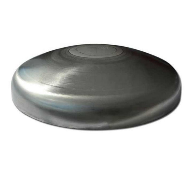
The flat head is the least efficient design, as it resists pressure primarily through bending, which results in significantly higher material requirements. In this case, the required thickness is 3.9120”, making it much heavier than other head types. Flat heads are generally used when a flat internal surface is essential for the process.
Several alternative methods reduce the weight of flat heads:
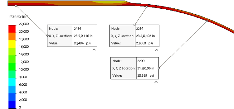
The ASME VIII-1 code formulas for cylinders and hemispherical heads are straightforward to derive. For the 0.5” thick cylinder, the calculated stress reaches the design limit of 20,000 psi. FEA using Tresca stress analysis yields a slightly higher value of 20,484 psi.
Similarly, the 0.2474” thick hemispherical head achieves a Tresca stress of 20,364 psi, closely matching the target value. These results confirm that both the cylinder and the hemispherical head meet the design stress requirements with excellent accuracy.
The stress at the discontinuity zone where the head meets the shell is higher, reaching 23,060 psi. ASME Section VIII, Division 2 (VIII-2) code rules permit localized stress increases over small distances, provided they remain within specified limits. In this case, the stress levels are deemed acceptable. By contrast, ASME Section VIII, Division 1 (VIII-1) rules do not account for these localized stresses beyond requiring a 3:1 taper. However, practical experience shows that this approach is reliable.
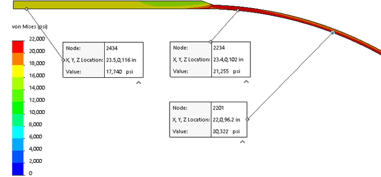
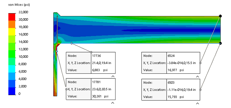
Tresca stress analysis shows a close correlation between the stress values predicted by VIII-1 code formulas and those obtained through finite element analysis (FEA) under VIII-2 guidelines for both the cylinder and the hemispherical head. However, ASME VIII-2 has transitioned from using the Tresca (P1-P3 stress) criterion to the von Mises stress formulation, providing a more comprehensive representation of stress behavior.
Von Mises stress in the cylinder and hemi head – the cylinder stress is now 12% below the VIII-1 code
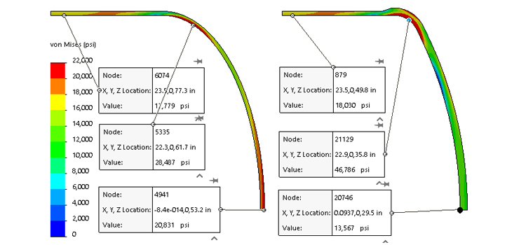
Be cautious using FEA for the design of these two head types because the knuckle stresses are in tension in the longitudinal direction (along the length of the shell) but can be compressive in the radial direction. The knuckle of these heads can buckle if made too thin.
As FEA methods are more commonly used, we expect that F&D head thicknesses (for large diameter thinner heads) will be higher. We do not expect SE head designs to change much.
Stresses in Flat Heads
VIII-1 formulas for flat heads result in heads that have center section stresses as calculated by FEA much lower than code rules allow. The flat head is in bending, which has allowable stresses of 1.5x membrane, or 30,000 psi in this case. The actual center stress is half of this. The code rules are more focused on the head to shell transition where an overbuilt head keeps the transition safe.
As designers get more freedom to use VIII-2 FEA methods in flat head design, where possible the heads will be made thinner all round, with more thickness in the center than the edges. These thinner heads will have more rotation at the head to shell junction requiring the designer to give this area much deserved attention. As FEA use becomes more common, we expect flat head thicknesses to reduce.
Head
Thickness [in]
Outside Height [in]
Volume [US gal]
Weight [lbs]
Cylinder, 24” long
0.5
24
180.25
506.7
Hemi
0.2474
23.75
117.7
245.5
SE *
0.4947
13.74
70.1
397.3
F&D *
0.8901
10.29
47.7
602.9
Flat
3.9120
3.91
0
1920.8
* Including the 1 ½” straight flange
Hemispherical Head (Hemi)
Semi-Elliptical Head (SE)
Flanged and Dished Head (F&D)
Flat Head
Stress Analysis with Finite Element Analysis (FEA)
Cylinder and Hemi Head Tresca Stresses
Cylinder and Hemi Head von Mises Stresses
Relevant News
